updated 2018
GREETINGS!!!
Welcome to the in-depth tutorial detailing the construction of a protocol droid lifesized prop replica. This tutorial will take you through each and every step in transforming the raw untrimmed kit components, into a fully finished gold plated museum quality statue.


UPDATE: NEW PARTS ADDED TO THE ARMS 2017. Plus new Tutorial videos!


UPDATE: The kit has been modified and no longer needs these two pieces:
 The abdomin ring is now replaced with finer detail on the chestplate and a smaller medallion inset.
The back plate inset is no longer needed due to finer detail incorporated into the final thermal form.

This demonstration kit is seen in more detail here:


UPDATE: NEW PARTS ADDED TO THE ARMS 2017. Plus new Tutorial videos!


UPDATE: The kit has been modified and no longer needs these two pieces:
The back plate inset is no longer needed due to finer detail incorporated into the final thermal form.
This demonstration kit is seen in more detail here:
A full head to toe kit looks like this: (click for fullsize views)
**please note that many detail parts were updated (neckring, arm groove details, knuckle and throat pistons, arm actuators, knee pistons, arm connection mechanics), so some of the base kit photos differ a tad bit.


Turn that kit into this:


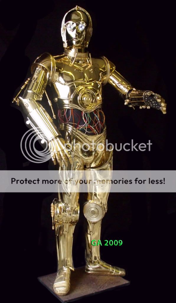


You'll notice that many of the body components of this kit are thermal formed shells that have been designed with missing 'high detail'. The 'high detail' areas are any surfaces that have hard edge ridges, rings, ribbing, piston protrusions, knobs, etc.. These details are separate hand-cast urethane parts. Once assembled, accuracy is completely maintained.


This technique was achieved to assist in the gold chroming process (thermal formed shells are the best substrate for gold chroming processes).
The rundown of the RESIN-CAST components are as follows: Horseshoe head ring, head bolts, head antenna, rear head port, eye grills, eye cups (transluscent), neckring, shoulder rings, both shoulder bells, abdominal ring, chest knobs, hip detail bricks, knee disks (4 total), feet, both hands, and an assortment of detail pieces composing the full piston and actuator sets for the legs and arms.
There are 12 main stages of assembly on this kit.
- Trimming
- Assembling shells
- Re-enforcing shells
- Final trimming
- High detail
- Attachments (armature assembly, magnetic armatures, wire armatures, etc..)
- Piston/Actuator construction
- Mid-section assembly
- Building the display base
- Final assembly
- Painting/Plating
- Optional electronics (lights & sound)
Tools needed for these steps include: Belt sander, bandsaw, power drill, sandpaper of various grits, dremel with various bits, CA glue with spray kicker, bondo, pvc cement, gorilla glue.
Materials needed (not included in the kit): apoxie sculpt (aves supply), rubber sheeting (ace hardware), wiring (radio shack), mdf board (home depot), 1" pvc stock and 1" pvc joints (home depot), sheet metal, wood screws and bolts (home depot), and 3" magnetic disks (available online).
This tutorial is broken down into stages, first depicting the assembly of individual body components, then attaching body parts to body parts where necessary, then final detail assembly where things like 'pinning actuators' and 'magnetic puck assembly' will be addressed. Lastly we'll look at adding electronics and sonic features.
NOTE: **If you are planning on creating a WEARABLE version, you will follow many of the same basic assembly steps, but you will not follow the "final assembly" areas since you want to keep your parts hollow.
We'll start with the head and work our way down to the feet. Here we go!!!!!!!!
THE HEAD
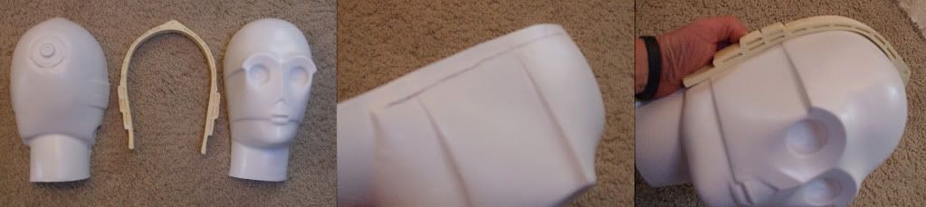
Let's start by looking at the kit components:

The head kit consists of 2 thermal formed shells comprising the face and back of the head, a horseshoe ring, neckring, 2 neckbolts, an antenna, 2 eye grills, a rear head port, PVC neck, and 2 transluscent eye cups.
Trim all the resin pieces on a belt sander and address any seamlines with sandpaper. Set all the pieces aside for now and concentrate on the head shells and the horseshoe ring.
Be sure to trim the FACEPLATE as shown (you must leave a lip at the end to allow for proper assembly. Use a pencil to draw in this line and make a center hashmark on the forehead to help you align the horsehoe ring. Adhere the resin horseshoe ring using superglue and spray accelerant. Be sure to test fit this to make sure you know where it aligns left and right. Don't fret if there are gaps in the sides. You will address that in the next step:

Once your horseshoe ring is in place, glue the rear headshell in place using superglue and spray
kicker. There may be a few areas that overlap beyond the horsehoe. Trim those areas away with a dremel. Now fill in the gaps with bondo.   |
Using the mini drum sanding bit on your dremel, take away the ear covering so the resin neckbolt slots
into place.


Now it's time to sand down the seamline. I like to add a piece of painters tape along the crown to prevent inadvertantly scratching the plastic surface. Sand down the bondo until you get a nice even finish. Several layers may be needed so be patient.

Using the same drum sanding bit, carefully remove the rear headport area to allow the resin replacement port to fit in tightly. Glue this into place from the interior. I drilled a hole in this sample to allow for an on/off switch (optional).


Alternate Head kit consists of: resin cast shell, 2 eye grills, antenna, 2 neckbolts, 2 transcluscent eye cups. (see below)


SHOULDERS


The trimming on the shoulders is very simple. Accomplish this on a belt sander. I use a 36" belt sander but you can do this with a smaller machine. First trim the flashing off the bottom. The rough trim the flashing in the center with a dremel (cutoff wheel attachment), then finish on a drum sander. That result will look like this:

HANDS

Each hand is 4 pieces(unless you're getting the wearable hands): a lightweight casting with 3 knuckle pistons. Use bondo and putty to fill any showing seamlines and move foward to:
ARMS

With the arm shells i'll show you the construction of the biceps separataely from the forearms. First the biceps:


When trimming the biceps, you can adjust the width of the final pieces by using a heatgun to reshape the countours. A few of the parts need adjusdment using this technique anyways but if you are going for a wearable suit, you can adjust them in even further to make skinnier pieces.
One you have the two shells on each side, user superglue and spray kicker to spot glue them into position. Now cover the interior seamlines with bondo, then PVC cement over the top to adhere the bondo to the plastic. Be sure to wipe off any excess PVC cement as it is caustic to the plastic surface. Once all this is dried you will have a VERY secure adhesion.
One you have the two shells on each side, user superglue and spray kicker to spot glue them into position. Now cover the interior seamlines with bondo, then PVC cement over the top to adhere the bondo to the plastic. Be sure to wipe off any excess PVC cement as it is caustic to the plastic surface. Once all this is dried you will have a VERY secure adhesion.
Now use the provided resin cast pieces to add the forearm knob in place, the piston tab, the high piston detail, groove plates, and piston head attachments.
FOREARMS

Like the biceps, the forearms need a little adjustment and, if you are making a wearable costume, customization to your body size. This is done using a heatgun. Be careful not too apply too much heat at once. Test your heatgun on some scrap plastic before proceeding. Once you are happy with the size, spotglue (CA glue and spray kicker), and hold in position with clamps until the glue is dried. Apply bondo, then pvc cement to the interior seamline for ultimate strength.

Next, trim the parts on a belt sander (showing above) and begin assembly using the provided resin detail components.
The above photo shows the new groove plates, forearm knobs, and piston attachment pins and how they are assembled on the forearms.

If you are converting this to a wearable costume, you can see that the arms, assembled according to the steps above, need no modifications. They can be custom trimmed and lined with foam for comfort.
To connect the bicep to the forearm, hollow out a pit into the upper forearm knob and drive a screw through the joint (shown above).
I used the magnet/metal plate method of attaching the arms to the body by creating a solid flat platform into the upper bicep. I used cardstock to fill the hollow space, then backfilled the gap wtih urethane resin (shown above). This can be done with bondo also. Once that's cured, trim it flat, and use construction adhesive and a screw to secure a metal plate (standard sheet metal trimmed to fit).
ARM PISTONS

These are the arm pistons (resin cast) provided with the kit. You can feel free to upgrade these with brass or aluminum rod pistons from a machine shop. But these are free of charge with each kit. Start by attaching the glass marbles onto the knee pistons, then, after you clean the parts with sandpaper and files, use a drill to assemble wood or plastic rods in place like this:

The INNER arm pistons attach at bicep using a cleaved open end (cleave it with a dremel cutoff wheel). The lower portion attaches at the forearm.
The OUTTER arm piston attaches with a cleaved pin attachment at the top, and a tongue and groove attachment at the elbow.

I left the piston rods untrimmed at the ends (with removeable attachment knobs). I left them much longer than is needed so I can custom pose the arms once the components are gold plated. Once a desired length is settled, you can trim the pistons, or leave the rods unglued so they are functional (slide in, slide out).
TRUNK


Note: when you assemble the trunk halves, have one of the resin shoulder rings and the neckring on hand. You can use these to make sure you're leaving yourself enough room for them later.
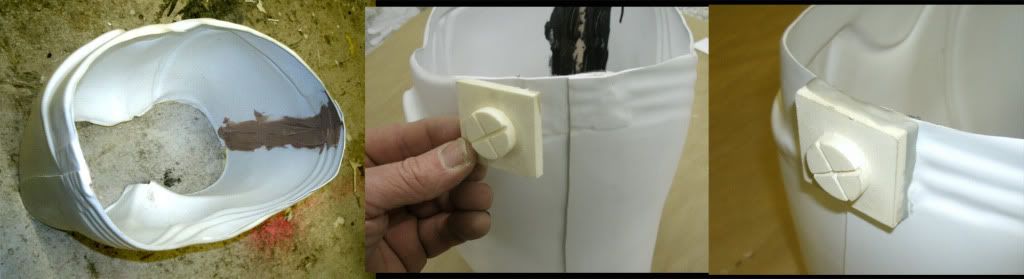
Dremel out the 'belly button' using a drum bit and inset the detail piece from the inside (see above).
Use your belt sander to trim down any excess plastic that raises above a flat surface level for the shoulders. The shoulder ring must lay flat. Once you are satisfied with the trimming use CA glue and clamps to hold the rings securely in place and spray kick them to make the bond permanent. The last photo showing above shows the placement of the chest detail pieces.
At this stage, use painters tape to secure off the seamlines on the shoulder rings. Cut two plywood disks that fit the interior of the shoulder. Use liberal amounts of bondo over the interior seamlines and press the wood disks deep into the shoulder. This provides for stength and also a mounting plate for your shoulder mangetic ring attachment. (see below)

Attach the NECKRING the same way you attached the shoulder rings. Trim the area flat on a belt sander, spotglue the neckring in place, cover the entire area with painters tape and backfill the INTERIOR with bondo to cover any gaps. A combo of bondo and aves apoxie sculpt will take care of any gaps (needed at the rear to blend the neckring into the backplate).

The 2 throat pistons attach like this (showing above). The rods do not lay against the neckring at all, they hover away from them, pointing upwards. Do this by attaching wire to the ends and feed the wires through the throat area. On the interior, bend the wires upwards so the tension holds the pistons up and away from the neckring. Use adhesive to seal their position. The throat medallion can now be glue in place also.
There are several ways to prepare the shoulders for the arm attachments. I did mine using magnets and metal plates. This allows for shoudler articulation and a wide range of poseability.

Use construction adhesive to secure the resin angle plate to the wood disk inside the shoulder joint. Let cure and then bolt a 6" magnet to the surface (shown above).

COMPLETED TORSO!! (minus the throat pistons which will be attached after gold plating is completed).


HIPS


The hips are very simple. They are composed of 4 parts: Front shell, back shell, and two detail pieces. Start by trimming the flash off the hips. The FRONT overlaps over the rear so leave plenty of flashing when trimming the rear hips.

Use clamps to hold the halves together and superglue/spray kick to adhere, then follow up with bondo and PVC cement. The detal bricks are trimmed nad glued on the sides at the tops. The gaps can be filled with either bondo or aves apoxie scupt (my favourite since you can sculpt it in and reduce your sanding time).


Use clamps to hold the halves together and superglue/spray kick to adhere, then follow up with bondo and PVC cement. The detal bricks are trimmed nad glued on the sides at the tops. The gaps can be filled with either bondo or aves apoxie scupt (my favourite since you can sculpt it in and reduce your sanding time).


THIGHS


Trim the thigh pieces as shown. The trimline is very easy to see on the kit pieces. Fit them together using painters tape to hold them. The legs need to be widened a little, and this is youir best opportunity to custom fit the legs to your legs if you are planning on buiding a wearable suit. I used black plastic of the legs shells and white plastic for the rear leg expansion piece to demonstrate how this looks. Spot glue/spray kick them.

Super glue/spray kick them to adhere, then re-enforce that with bondo & pvc cement. Use the belt sander to trim excess off the edges. (showing above)


SHINS


Sometimes you will end up with an uneven surface where the knee disks attach. Address this by filling the interiors of those areas with foam, then sand the disk area flat on a belt sander.
Then use superglue to adhere the 4 knee disks in place (showing above). Clamps help hold them tightly while the glue dries. Use a belt sander to trim any excess areas (last photo shows trimmed ankle area.
FEET
The Feet are simple. Just trim the bottom flashing on a belt sander.
_________________________________________________________
ASSEMBLY STAGES
Now we move onto the ASSEMBLY stages of this project. Now that you have all the pieces assembled as separate body parts, you will need to bring them together to form your display statue. If you plan on gold plating your components, not all of the assembly can be done at this stage. My example on this page shows your assembly process if you plan on going for a gold chromed or painted finish.
***please note: If you are planning on building a wearable costume, you will follow NONE of these steps. Now that you have individual body parts, it's your job to separate the pieces and do heavy modifications to create wearable/closeable shells. Those steps will not be addressed in this tutorial. Soooo.. good luck to you!!
Assembly should begin from the bottom up. Once you have assembled a display base (see that section in this tutorial), you can use that to start on the legs. Trim your feet so that a 1" pvc pipe can feed through the middle. Place your foot over the female pvc joint that's mounted onto the base, and cover the gaps with clay. You don't want any foam seaping through the foot onto the base.
Now insert a 1" pvc pipe into the fitting throug the foot. Measure this pipe to about the top of the thigh (see photos below).
Now insert a 1" pvc pipe into the fitting throug the foot. Measure this pipe to about the top of the thigh (see photos below).

You want the seal between the shin bottom and the foot to be pretty much airtight. Do this by using more clay. Once you're happy with the seal, pour in some expanding foam and let it rise. This does TWO things: 1.) It adheres the foot to the pvc pipe, and the shin to the foot.

Now do the same steps for the thighs. Insert them into position on top of the shins, trim them where necessary so they sit low down. Make the connection watertight by using clay (water based clay is easiest to work with). Once you're happy with the seal, pour in expanding foam. Your result will be thighs that are locked onto the shins which are locked onto the feet which have a pvc interior that locks onto any 1" pvc female joint. The advantage to this is you can mount the statue ANYWHERE you mount a 1" pvc joint.
The posts in the interior of each foot can be re-enforced by filling in their connection area with resin or fiberglass. When doing this make sure to leave plenty of slack at the end of the post (where it will attach to your base).
The posts in the interior of each foot can be re-enforced by filling in their connection area with resin or fiberglass. When doing this make sure to leave plenty of slack at the end of the post (where it will attach to your base).

Use putty (e.g. aves apoxy sculpt) to fill any gaps. Smooth and sand when cured.

YOU'RE DONE WITH THE LEGS!
Attach the knee pistons using some plastic coated aluminum wire (home depot).
Drill the hips onto the tops of the thighs to test fit. It should now look like this:

If you followed the steps, you'll have two sections of equal length PVC acting as "femurs". These are firmly connected to the shins, which are connected to the feet, which are solidy planted onto the base (removeable if you twist each leg off the posts). With the hips attached it looks like this:

Use 2 90 degree pvc joints at the tops of the femers. These are connected by a 4 way pvc joint. Some adjustment may be necessary to allow enough room to fit the 4-way joint. You may need to bend the pvc outwards and then inwards to allow this fitting. You can easily re-shape the pvc by heating it up with a painters heatgun and bending it.

Once you have the 4-way joint centered in place, you'll need to cut another section of pvc to create the 'spine'. The spine needs to stand straight up so more adjustment (using a heatgun) may be necessary.

Use another 4-way joint at the top of the spine and attach a few short lenghts of pvc. This "T" creates support for the trunk. Trim the spine (from the top) to the proper length so the trunk sits at the correct height (showing above). Slide the trunk down.
**NOTE during FINAL assembly, you'll probably want to strengthen the joint where the spine meets the hips by using pvc cement to permanently lock the spine in position. You'll still be able to disassemble the skeleton but some pvc cement to lock the joints will prevent the skeleton from leaning forwards or backwards.

One more length of pvc will create the support for the head (shown above).
A rough assembly now looks like this!:


The main assembly/prep work neeed prior to gold plating or painting is COMPLETED!!! If you plan on having the parts gold plated, you'll want to scrub them clean and degrease all the surfaces with special solvents to prep the surface.
Once you have all this work done to the hard components, the only thing left to do at this point is create:
THE RIBBED RUBBER MID-SECTION
The base material of the mid-section can be made of any kind of rubber or fabric material that has the proper ribbing texture. The ribber rubber sheeting seen in this tutorial can be found in the flooring section at ACE HARDWARE. Have them cut enough material to cover the length of the midsection *your waist measurement if you are going for a wearable version. Leave enough extra material to overlap itself by a few inches.


Now you'll need zip ties to help with the assembly of the wires. The wires can be found new at electronic stores or, if you're on a budget, head to a junkyard with some cutting shears or a saw and gather a few wire harnesses from under a hood of an old car. For some reason 80s VOLVOS have harnesses that are the easiest to access.

If the wires are especially greasy and dirty, I suggest washing them by soaking them in acetone for a few minutes to de-grease them. Now you're ready to assemble the wiring. Avoid using BLACK wires, and concentrate mainly on the blue, yellow, green, white and red cables. Clump the wires together in colorful groups and apply them across the rubber surface. Use a drill (or hole puncher) and create holes for your zipties. Try to be as random as possible.

Continue applying the wiring until you're happy with their populations. The photo above shows a mostly finished mid-section. I will go back after final assembly and detail a bit more with thicker wires strategically placed to accentuate the look (and hide exposed zip ties).

The strongest method of attaching the rubber midsection to the hips is to screw them directly into the sides of the hips (where the bricks are at the sides). Drill a pilot hole, and then use a 1/4" screw to connect the rubber to the hips. Do this on both sides. Now you can use some construction adhesive to permanently bond these components together.
Results:

PAINTING/PLATING
In this example, I had the parts professionally gold plated. You can contact me (impervium@hotmail.com) for this plating work (about $1200 for a full head to toe body). Parts must be separated to be plated properly so once you get them back you'll need to do some assembly and detail work. The collection of plated parts looks like this:

Let's start with the HANDS/ARMS assembly.

Use flat-black acrylic paint to paint out the palm area of both hands. Leave the gold tabs as shown. Once the paint is dry, you can detail even further by drilling small holes and feeding wires that connect the fingers to the palms (see below).

The hands can be attached to the forearms by using construction adhesive (applied from the interior) and letting the glue cure overnight. There is an empty space between the forearm and the upper arm. You can fill in this area by using some rubber sheeting (same as used for the mid-section). Cut a large rectangle and hotglue into the upper forearm as shown below.

FINISHED ARMS


SHOULDER JOINT ASSEMBLY
In an earlier step I showed you how the magnetic disk is attached at the shoulder joint, and how we attached the metal endcap onto the end of the upper arm. That takes care of the arm attachment. But now we need to address the SHOULDER RING articulation.
As the arm moves on its 360 rotation, the shoulder bell must necessarily move along with it. This problem is achieved with the use of a metal ring on the shoulder ring surface, and corresponding earth magnets embedded directly into the shoulder bells.

Start by cutting a disk out of sheet metal. Drill holes and screw down the disk onto the shoulder ring. (shown above)


Now use a dremel to make 4 hollow mount locations for mini earth magnets (ACE hardware). Hotglue the mini magnets in place. These are VERY POWERFUL magnets and will hold the shoulder bells in place at any rotation point.
FINISHED TORSO


To begin the FINAL ASSEMBLY, attach the finished legs onto the base, then bolt the hips onto the legs. (showing below)


Drill a hole through the piston attachment points and connect with a thin piece of coated wire. (showing above).
ELECTRONICS
Electronics for a project like this can involve: 1.) Lights (in the eyes) 2.) Sound (with the use of a sound board) and 3.) Movement.
First, let's address the LEDs to light up the eyes.


The first step at this stage is preparing the eyes to accept the eye components and electronics. Dremel out the sockets and trim down the transluscent eye cups so they fit in tightly.

The antenna can be simply glue on, but I prefer a stronger method. Drill a wire into the body of the antenna and then a corresponding hole in the horseshoe. Apply a few dabs of glue, a little accelerant and VOILA!

Next, you want to attach the pvc neck. Do this by driving 2 wood screws through the bottom-most end of the horseshoe and connecting through the pvc. Hotglue
your neckbolts once this is done.
your neckbolts once this is done.
The eyegrills will need a little trimming to fit over the sockets. The fastest way to do this is on a belt sander. A little dab of black paint over the iris & mouth completes the look.

OPTIONAL ELECTRONICS
An additional option you may want to explore is adding LEDs inside the eyes. You can do this buy either purchasing a driver board for 6 warm white leds or creating your own circuitry.
An additional option you may want to explore is adding LEDs inside the eyes. You can do this buy either purchasing a driver board for 6 warm white leds or creating your own circuitry.
Feed the LED groups separately through each eye socket. Drill 3 5mm holes into each eyecup and hotglue the LEDs into the underside. Once the glue is cured pop the eyes back into their position and glue in place from the interior.

Be sure to check the LEDs and the on/off switch to make sure everything is working properly and the wires are securely in place (no flickering etc..) The best spot for the on/off switch/button/toggle is the rear headport. Here I am using a toggle, installing it using a piece of epoxie putty from the interior. Allow this to cure overnight before you flip the switch.


COMPELTED!!!!!!!!

Photo above shows the poseabilty of the arms (full 360 rotation with full shoulder bell articulations (thanks to the metal plates and magnetic engineering).

email impervium@hotmail.com


You have discussed an interesting topic that everybody should know. Very well explained with examples. I have found a similar website Home Safe visit the site to know more about Access Controls Melbourne.
ReplyDeleteThis comment has been removed by the author.
ReplyDeleteCould u please send me the full blueprints and full instructions for building C3PO droid
ReplyDelete